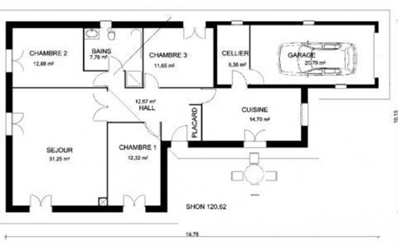
In architecture and building engineering, a floor plan is a drawing to scale, showing a view from above, of the relationships between rooms, spaces and other physical features at one level of a structure.
Dimensions are usually drawn between the walls to specify room sizes and wall lengths. Floor plans may also include details of fixtures like sinks, water heaters, furnaces, etc. Floor plans may include notes for construction to specify finishes, construction methods, or symbols for electrical items.
It is also called a which is a measured plane typically projected at the floor height of 4 ft (1.2 m), as opposed to an which is a measured plane projected from the side of a building, along its height, or a section or where a building, is cut along an axis to reveal the interior structure.
Overview[edit]
Similar to a map the orientation of the view is downward from above, but unlike a conventional map, a plan is drawn at a particular vertical position (commonly at about 4 feet above the floor). Objects below this level are seen, objects at this level are shown 'cut' in plan-section, and objects above this vertical position within the structure are omitted or shown dashed. Plan view or planform is defined as a vertical orthographic projection of an object on a horizontal plane, like a map.
The term may be used in general to describe any drawing showing the physical layout of objects. For example, it may denote the arrangement of the displayed objects at an exhibition, or the arrangement of exhibitor booths at a convention. Drawings are now reproduced using plotters and large format xerographic copiers.
A reflected ceiling plan (RCP) shows a view of the room as if looking from above, through the ceiling, at a mirror installed one foot below the ceiling level, which shows the reflected image of the ceiling above. This convention maintains the same orientation of the floor and ceilings plans - looking down from above. RCPs are used by designers and architects to demonstrate lighting, visible mechanical features, and ceiling forms as part of the documents provided for construction.
Building blocks[edit]
A floor plan is not a top view or birds eye view. It is a measured drawing to scale of the layout of a floor in a building. A top view or bird's eye view does not show an orthogonally projected plane cut at the typical 4 foot height above the floor level. A floor plan could show:
- Interior walls and hallways
- Restrooms
- Windows and doors
- Appliances such as stoves, refrigerators, water heater etc.
- Interior features such as fireplaces, saunas and whirlpools
- The use of all rooms
Plan view[edit]
A plan view is an orthographic projection of a 3-dimensional object from the position of a horizontal plane through the object. In other words, a plan is a section viewed from the top. In such views, the portion of the object above the plane (section) is omitted to reveal what lies beyond. In the case of a floor plan, the roof and upper portion of the walls may typically be omitted.
Roof plans are orthographic projections, but they are not sections as their viewing plane is outside of the object.
3D Floor plans[edit]
Despite the purpose of floor plans originally being to depict 3D layouts in a 2D manner, technological expansion has made rendereing 3D models much more cost effective. 3D plans show a better depth of image and are often complimented by 3D furniture in the room. This allows a greater appreciation of scale than with traditional 2D floor plans.
Examples[edit]
- Typical U.S. basic house floor plan.
RELATED VIDEO
RELATED FACTS
-
 In architecture and building engineering, a floor plan, or floorplan, is a drawing to scale, showing a view from above, of the relationships between rooms, spaces and other physical features at one level of a structure.
Dimensions are usually drawn between the walls... - The South Dakota State Capitol is the state capitol building of the U.S. state of South Dakota. Housing the South Dakota State Legislature, it is located in the state capital of Pierre at 500 East Capitol Avenue. The building houses the offices of most state...
Share this Post
latest post
-
 Helpful October 4, 2022
 -
 FAQ October 4, 2022
 -
 Reference Guide October 4, 2022
 -
 Guidebook October 4, 2022
 -
 Reference Book September 1, 2022
 -
 Manual September 1, 2022
 -
 Handbook September 1, 2022
 -
 Resources August 24, 2022
 -
 Software architecture and Design Patterns June 14, 2022