 By Ellen Finkelstein
Are you getting the look you need for your dimensions? Are you constantly making little adjustments? If dimensions aren’t your friend, you need to get more comfortable with dimension styles.
In this tutorial, you create an architectural dimension style. Why? Because the default style is a mechanical look and by changing it to architectural, you’ll get a chance to work with many of the dimension style features.
Note: The values that I chose in this tutorial are my choices. They don’t come from any standard; you should follow the standards in your office or discipline.
Follow these steps:
Open any architectural drawing. If you don’t have one, open a new drawing and choose Format > Units. Change the units to architectural. Draw a rectangle 40′ wide by 30′ high and zoom to its extents. Zoom out a little more so you have room for your dimensions.
If you’re starting with a new drawing, create a new layer, named dim and make it a different color from your rectangle. Set it current. Make sure that OSNAP is on with a running object snap for endpoints.
Choose Dimension > Dimension Style or click Dimension Style on the Dimension toolbar to open the Dimension Style Manager.
Click New. In the Create New Dimension Style dialog box, enter arch_96 and click Continue. The 96 refers to the scale that we’ll use later.
Note: We won’t use it now, but click the Use For drop-down list. You can see that you can create a style that applies only to a certain type of dimension. For example, you may want angular dimensions to have open arrows but the rest of your dimensions to use architectural ticks. So you could create a dimension style just for angular dimensions.
Click Continue.
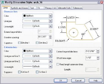
The New Dimension Style: arch_96 dialog box opens. Click the Lines tab.
Note: In the Dimension Lines section, you can make the dimension line’s color, linetype, and ineweight different from the rest of the dimension. We’ll leave it the same, which is more typical.
Note that the Extend Beyond Ticks box is grayed out. That’s because you don’t have architectural ticks (and I hope you don’t have any other kind either). To create the ticks, click the Symbols and Arrows tab. In the Arrowheads section, choose Architectural tick from the First drop-down list. The Second drop-down list follows suit automatically. Choose Open from the Leader drop-down list. The arrow size should be 3/16″.
Click the Lines tab again. Set the Extend Beyond Ticks value to 1/16″.
Leave the Baseline Spacing value at 3/8″. This is the spacing between the dimension lines of two baseline dimensions.
Note: You can suppress the first or second dimension line. These are the lines to the left or right of the text. As you’ll see later, architectural dimensions only have one dimension line, so this doesn’t apply to us.
In the Extension Lines section, you can change the color, linetype, and lineweight of the extension lines. We’ll leave them unchanged.
Note: You can also suppress the first or second extension line. Normally, you would do this only for a special situation where an extension line doesn’t fit well. You would create an override to a dimension style for this purpose. (That’s for another tip!)
Change the Extend Beyond Dim Lines value to 1/8″. This is the amount that the extension lines extend beyond the dimension lines.
RELATED VIDEO


 Architecture (Latin architectura, from the Greek ἀρχιτέκτων – arkhitekton, from ἀρχι- "chief" and τέκτων "builder, carpenter, mason") is both the process and product of planning, designing and construction. Architectural works, in the material form of buildings, are...
 An architectural style is a specific method of construction, characterized by the features that make it notable. A style may include such elements as form, method of construction, materials, and regional character. Most architecture can be classified as a chronology...


